Introduction
MINA is an open instruction set architecture (ISA) designed to be extendable and easy to decode.
Current and future goals include:
An ISA suitable for hardware implementation.
32-bit and 64-bit address space variants.
MINA ISA Overview
The MINA ISA is defined as a base integer ISA with optional floating-point, SIMD and user-defined extensions. Current base integer ISAs are MINA32 and MINA64, which has not been defined yet.
Planned extensions include FloatingMINA (floating-point) and VectorMINA (single instruction, multiple data).
Events, Faults And Interrupts
Unusual conditions occurring at run time are referred to as events.
Faults are events that occur synchronously to the current MINA thread; they transfer control to a fault handler.
Interrupts are similar to faults. However, interrupts occur asynchronously to the current MINA thread.
Data Types
The MINA ISA currently defines the following data types:
Byte (8-bit)
Halfword (16-bit)
Word (32-bit)
Longword (64-bit)
Future versions of the MINA ISA will define more data types.
Machine Control Register
The Machine Control Register (MCR) is a longword register displaying information about the current state of a MINA implementation. It is accessible through special move and load-store instructions.
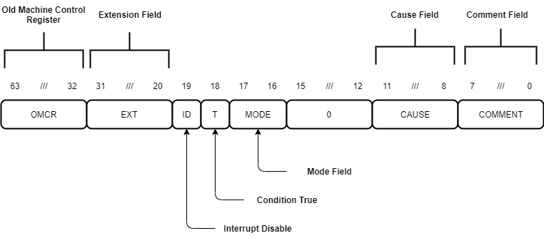
Figure 1: Machine Control Register
OMCR (Old Machine Control Register) is a special 32-bit field holding a copy of the low 32 bits of MCR during fault handling.
EXT (Extension) is a read-only 12-bit field.
All bits in this field indicate the presence or absence of certain instruction extensions.
Writes to this field are ignored. Undefined bits are hardwired to low.
Bit |
Extension |
|---|---|
0 |
Division |
1 |
Cache Control |
6 |
FloatingMINA |
7 |
VectorMINA |
8 |
User Extension 1 |
9 |
User Extension 2 |
10 |
User Extension 3 |
11 |
User Extension 4 |
ID (Interrupt Disable) controls the generation of External Interrupt faults.
When this bit is high, interrupts do not generate External Interrupt faults.
Note
The state of ID does not affect the operation of the WFI instruction.
T (Condition True) controls the execution of predicated instructions.
T variants execute when this bit is high, F variants execute when this bit is low.
MODE (Mode) is a 2-bit field determining the current processor operating mode.
MODE[1:0] |
Mode |
Visible Registers |
|---|---|---|
00 |
User |
r0-r7, r8_usr-r15_usr |
01 |
Supervisor |
r0-r7, r8_svc-r15_svc |
10 |
Reserved |
|
11 |
Reserved |
Warning
Writing Reserved values to this field generates an Invalid State fault.
During fault processing, the current fault cause is loaded into the 4-bit CAUSE (Cause) field.
On reset, this field is 1111.
CAUSE[3:0] |
Fault Cause |
|---|---|
0000 |
Misaligned Load Address |
0001 |
Misaligned Store Address |
0100 |
Invalid State |
0101 |
Privilege Mismatch |
1000 |
Undefined Instruction |
1100 |
External Interrupt |
1101 |
User Interrupt |
1110 |
Supervisor Call |
1111 |
Reset |
Note
It is possible to program undefined values into CAUSE. However, this is discouraged as future versions of MINA may define these values. To avoid software incompatibilities, use User Interrupt for user-defined faults.
COMMENT (Comment) is an 8-bit field that can be used to pass information from the current User mode thread to the Supervisor mode thread.
The SVCALL and FAULT instructions write a user-defined value into this field.
The Stack
MINA uses a full-descending stack model. Push operations decrement the stack pointer before writing data onto the stack. Pop operations increment the stack pointer after loading data from the stack.