MINA32 Base Integer Instruction Set, Version 1
The following sections describe version 1 of the MINA32 base integer ISA.
Overview
MINA32 has a total of 27 registers:
24 32-bit general-purpose registers.
2 system registers.
user-visible 32-bit program counter.
General-purpose registers r0-r7 are shared across all modes, r8-r15 are mode-specific.
Note
r15 is used as a stack pointer (SP) for instructions that use the stack. At all other times you can treat r15 as a general-purpose register.
Note
It is possible to access User mode registers r8_usr-r15_usr from Supervisor mode through the use of special move instructions.
The two system registers are MCR - the Machine Control Register - and FRET - the Fault Return Address register.
While limited MCR access is possible in User mode, FRET is only visible to Supervisor mode threads.
The user-visible program counter (PC) holds the address of the currently executing instruction.
Fault Entry And Exit
MINA faults are handled as follows:
Depending on the fault cause, FRET is loaded with
PCorPC + 4.MCR is left-shifted by
32.IDis pulledhigh,MODEis set to10(Supervisor).CAUSEis loaded with an appropriate fault code.In case of a user-generated fault,
COMMENTis loaded with a user-defined 8-bit value.PCis set to0.
To return from a fault, a fault handler must use the SWITCH instruction.
SWITCH restores MCR by right-shifting it by 32 and resets PC to the value stored in FRET.
Instruction Formats
There are five core instruction formats (S/I/M/F/B).
Instructions must be aligned on a four-byte boundary; misaligned instructions generate Misaligned Load Address faults.
The S-type (Standard) format is used for most instructions that operate on registers.

Figure 2: S-type Format
The I-type (Immediate) format is the default register-immediate format.
An I-type immediate is sign-extended 12-bit data (IMM[11:0]) left-shifted by the shift amount specified in SHIFT.
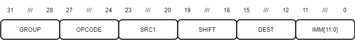
Figure 3: I-type Format
The M-type (Move) format is a special register-immediate format.
An M-type immediate is zero-extended 16-bit data (IMM[15:0]) left-shifted by 0 (MOVL instruction) or 16 (MOVU instruction).
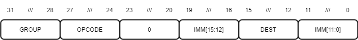
Figure 4: M-type Format
The F-type (Funnel Shift) format is a special register-register format with four register operands.

Figure 5: F-type Format
The B-type (Branch) format is a special immediate format.
A program counter-relative branch offset is sign-extended 24-bit data (IMM[23:0]) left-shifted by 2.

Figure 6: B-type Format
Instruction Summary
Arithmetic/Divide/NOP Group (0000)
Opcode |
Mnemonic |
Instruction |
Format |
|---|---|---|---|
0000 |
ADDI |
Add Immediate |
I |
0001 |
MULTI |
Multiply Immediate |
I |
0010 |
DIVI |
Divide Immediate |
I |
0011 |
REMI |
Compute Remainder Immediate |
I |
0100 |
SLTI |
Set If Less Than Immediate |
I |
0101 |
SLTIU |
Set If Less Than Immediate Unsigned |
I |
0110 |
NOP |
No Operation |
I |
0111 |
PCADDI |
Add Program Counter Immediate |
I |
1000 |
ADD |
Add Register |
S |
1001 |
MULT |
Multiply Register |
S |
1010 |
DIV |
Divide Register |
S |
1011 |
REM |
Compute Remainder Register |
S |
1100 |
SLT |
Set If Less Than Register |
S |
1101 |
SLTU |
Set If Less Than Register Unsigned |
S |
1110 |
SUB |
Subtract Register |
S |
1111 |
PCADD |
Add Program Counter Register |
S |
Logic/Bitwise Group (0001)
Opcode |
Mnemonic |
Instruction |
Format |
|---|---|---|---|
0000 |
ANDI |
Logical AND Immediate |
I |
0001 |
ORI |
Logical OR Immediate |
I |
0010 |
XORI |
Logical XOR Immediate |
I |
0011 |
NANDI |
Logical NOT-AND Immediate |
I |
1000 |
AND |
Logical AND Register |
S |
1001 |
OR |
Logical OR Register |
S |
1010 |
XOR |
Logical XOR Register |
S |
1011 |
NAND |
Logical NOT-AND Register |
S |
1100 |
POPCNT |
Compute Population Count |
S |
1101 |
CLO |
Count Leading Ones |
S |
1110 |
PLO |
Find Position Of Leading One |
S |
Compare Group (0010)
Opcode |
Mnemonic |
Instruction |
Format |
|---|---|---|---|
0000 |
CMPI/EQ |
Compare Equal Immediate |
I |
0001 |
CMPI/LO |
Compare Lower Immediate |
I |
0010 |
CMPI/LS |
Compare Lower Or Same Immediate |
I |
0011 |
CMPI/LT |
Compare Less Than Immediate |
I |
0100 |
CMPI/LE |
Compare Less Than Or Equal Immediate |
I |
1000 |
CMP/EQ |
Compare Equal Register |
S |
1001 |
CMP/LO |
Compare Lower Register |
S |
1010 |
CMP/LS |
Compare Lower Or Same Register |
S |
1011 |
CMP/LT |
Compare Less Than Register |
S |
1100 |
CMP/LE |
Compare Less Than Or Equal Register |
S |
Register Branch Group (0011)
Opcode |
Mnemonic |
Instruction |
Format |
|---|---|---|---|
0000 |
RBRA |
Register Branch, Immediate Offset |
I |
0001 |
RCALL |
Register Call, Immediate Offset |
I |
0010 |
RET |
Return From Subroutine Call |
I |
1000 |
ROBRA |
Register Branch, Register Offset |
S |
1001 |
ROCALL |
Register Call, Register Offset |
S |
Memory Group (0100)
Opcode |
Mnemonic |
Instruction |
Format |
|---|---|---|---|
0000 |
LD |
Load Word, Immediate Offset |
I |
0001 |
LDH |
Load Halfword, Immediate Offset |
I |
0010 |
LDB |
Load Byte, Immediate Offset |
I |
0011 |
ST |
Store Word, Immediate Offset |
I |
0100 |
STH |
Store Halfword, Immediate Offset |
I |
0101 |
STB |
Store Byte, Immediate Offset |
I |
0110 |
LDC |
Load Machine Control Register |
I |
0111 |
STC |
Store Machine Control Register |
I |
1000 |
RLD |
Load Word, Register Offset |
S |
1001 |
RLDH |
Load Halfword, Register Offset |
S |
1010 |
RLDB |
Load Byte, Register Offset |
S |
1011 |
RST |
Store Word, Register Offset |
S |
1100 |
RSTH |
Store Halfword, Register Offset |
S |
1101 |
RSTB |
Store Byte, Register Offset |
S |
1110 |
POP |
Pop Word |
S |
1111 |
PUSH |
Push Word |
S |
Move Group (0101)
Opcode |
Mnemonic |
Instruction |
Format |
|---|---|---|---|
0000 |
MOVI |
Move Immediate |
I |
0001 |
MTI |
Move If True Immediate |
I |
0010 |
MFI |
Move If False Immediate |
I |
0011 |
MOVL |
Move Lower Immediate |
M |
0100 |
MOVU |
Move Upper Immediate |
M |
1000 |
MOV |
Move Register |
S |
1001 |
SEL |
Select Register |
S |
1011 |
MTOC |
Move To Machine Control Register |
S |
1100 |
MFRC |
Move From Machine Control Register |
S |
1101 |
MTOU |
Move To User Mode Register |
S |
1110 |
MFRU |
Move From User Mode Register |
S |
Shift Group (0110)
Opcode |
Mnemonic |
Instruction |
Format |
|---|---|---|---|
0000 |
LSL |
Shift By Immediate, Logical Left |
I |
0001 |
LSR |
Shift By Immediate, Logical Right |
I |
0010 |
ASR |
Shift By Immediate, Arithmetic Right |
I |
0011 |
ROR |
Rotate By Immediate, Right |
I |
1000 |
RLSL |
Shift By Register, Logical Left |
S |
1001 |
RLSR |
Shift By Register, Logical Right |
S |
1010 |
RASR |
Shift By Register, Arithmetic Right |
S |
1011 |
RROR |
Rotate By Register, Right |
S |
1100 |
FLSL |
Funnel Shift, Logical Left |
F |
1101 |
FLSR |
Funnel Shift, Logical Right |
F |
Control Group (0111)
Opcode |
Mnemonic |
Instruction |
Format |
|---|---|---|---|
0000 |
STOP |
Shut Down Processor |
I |
0001 |
WFI |
Wait For Interrupt |
I |
0010 |
SETT |
Set T Bit |
I |
0011 |
CLRT |
Clear T Bit |
I |
0100 |
SWITCH |
Switch To Saved State |
I |
1000 |
SVCALL |
Supervisor Call |
S |
1001 |
FAULT |
Generate Fault |
S |
1010 |
MTOF |
Move To Fault RetAddr Register |
S |
1011 |
MFRF |
Move From Fault RetAddr Register |
S |
1100 |
MTOC2 |
Move To OMCR |
S |
1101 |
MFRC2 |
Move From OMCR |
S |
PC-Relative Branch Group (1000)
Opcode |
Mnemonic |
Instruction |
Format |
|---|---|---|---|
0000 |
BRA |
PC-Relative Branch |
B |
0001 |
BT |
PC-Relative Branch If True |
B |
0010 |
BF |
PC-Relative Branch If False |
B |
1000 |
CALL |
PC-Relative Call |
B |
1001 |
CT |
PC-Relative Call If True |
B |
1010 |
CF |
PC-Relative Call If False |
B |
Instruction Set
ADD (Add Register): Arithmetic Instruction

Figure 7: ADD
Assembler syntax: add dest, src1, src2
Description: Adds register src1 to register src2 and stores the result in register dest.
Operation:
ADD(src1, src2, dest)
{
    r[dest] = r[src1] + r[src2];
}
ADDI (Add Immediate): Arithmetic Instruction
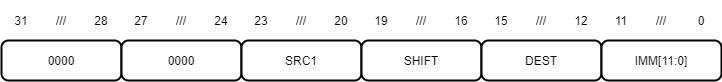
Figure 8: ADDI
Assembler syntax: addi dest, src1, imm
Description: Adds shifted sign-extended 12-bit immediate imm[11:0] to register src1 and stores the result in register dest.
Operation:
ADDI(src1, imm, shift, dest)
{
    imm = exts12(imm) LSL shift;
    r[dest] = r[src1] + imm;
}
Note
Since the 12-bit immediate is sign-extended, this instruction can add and subtract immediate data.
AND (Logical AND Register): Logic Instruction
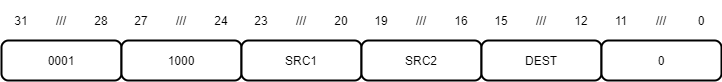
Figure 9: AND
Assembler syntax: and dest, src1, src2
Description: Logically ANDs register src1 with register src2 and stores the result in register dest.
Operation:
AND(src1, src2, dest)
{
    r[dest] = r[src1] AND r[src2];
}
ANDI (Logical AND Immediate): Logic Instruction
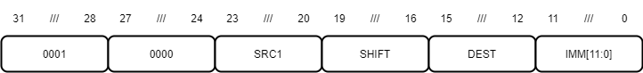
Figure 10: ANDI
Assembler syntax: andi dest, src1, imm
Description: Logically ANDs register src1 with shifted sign-extended 12-bit immediate imm[11:0] and stores the result in register dest.
Operation:
ANDI(src1, imm, shift, dest)
{
    imm = exts12(imm) LSL shift;
    r[dest] = r[src1] AND imm;
}